
Continuing the discussion started with representing System 2 – coordination, we present some ideas on how to represent recursive decomposition of System 1 units. Here, we use the idea from [10] to represent organizational borders via assigning each organization or unit, in our case, a color and use this color for borders of processes and assets that fall into the responsibility of each organization/unit. In this case, each unit will be identified as a set of processes and assets for which it is responsible. Note that if a unit is responsible for an asset, it is assumed that it will be responsible for the processes to manage this assets as well. The latter is not mandatory in all cases, though, the assets can be manged by an upper unit.
Two other features of FEM toolkit are used to represent the decomposition (see the diagram below.):
- Ghosts. A ghost is a copy of an original shape that can be placed in the same diagram or in another one. A ghost shape has an arrow in the upper right corner, clicking on which leads to the focus is moved to the original shape. A shape can have any number of ghosts, and there are navigation tools in the toolkit to find all occurrences of the same shape.
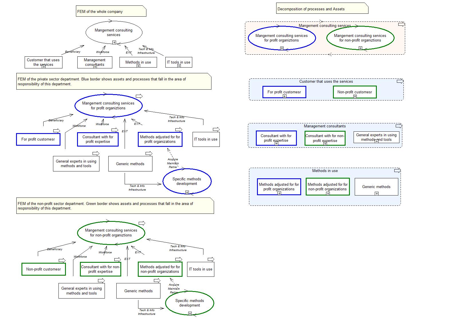
- Groups. A ghost can be converted into a group, which has a dashed boarder. Other shapes of the same type as the group can be placed inside it presenting the decomposition of the original shape, see the right-hand side of the diagram below. The semantic of decomposition can vary, the decomposition can show the variants, as in the decomposition of the process in the diagram, or parts, as in the decomposition of the assets in the diagram.
The diagram below shows a decomposition of a management consulting company that has two departments: one working with private organizations, the other one working with public sector and interest organizations. The decomposition of processes and assets is shown on the right-hand side of the diagram, while the left-hand hand side shows the FEM structures of System 1 units (departments). Note that some assets are not included in units, but are provided by the main company (IT-tools and experts). These assets have no border coloring. Each of the department can in turn be decompose in the same way, which can be shown on separate diagrams.
You can play with the diagram above in your FEM toolkit by importing the following library (unzip and use ADL import in Import/Export menu).